
Part 1 HERE, Part 2 HERE
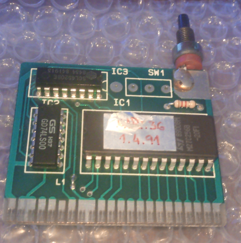
So far we have dissected one cartridge, which is fairly similar to a regular 16k C64 cartridge, apart from the ability to remove itself permanently from the memory map until reset. Next up is a bit more complex cartridge, with the ability to have up to 64k of programs inside. The banking scheme is very simple, but it took me a while to figure out what is going on. There were various versions of the same PCB, and interestingly, instead of TTL logic ICs, most of them use CMOS 40xx series of logic.
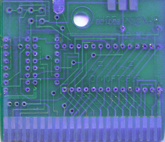
As always, the analysis started with desoldering all of the ICs and tracing the connections. This was accomplished with success, as the PCB had trough-plated holes. I noticed that there is something like a jumper block in the top left corner of the PCB, but the wiring was, at first glance, confusing. Some outputs from the logic ICs were connected to the power supply. At second glance. I noticed that some of the holes were drilled with a slightly larger drill bit. This was done after the PCB was made, to break the hole plating, and to break the connection between layers at those spots. How clever! Now, onto the analysis.
Logic circuit consists of a 4-gate 2-input NAND IC CD4011, and a Dual Binary Up-Counter CD4520. Similar to the previous cartridge, it is wired as a 16k cartridge, with /OE tied to the result of ANDing /ROMH and /ROML trough two NAND gates in the 4011. The two counters in the 4520 have two functions. The first counter acts as a bank-switching mechanism, with its outputs tied to A14 and A15 of the EPROM.

The second counter is used to disable the EPROM and drive /EXROM and /GAME high to remove the cartridge from the memory map. As clock inputs for the counters, /IO1 and /IO2 are used respectively. Inverted RESET signal is connected to both counters. The feedback from the first unused output on the banking counter is used as a locking mechanism for the banking counter, which inhibits any further attempts to drive the clock signal of that counter. On the second counter, the first output is used in similar fashion, and this counter actually performs the same function as the flip-flop on the cartridge from Part 2.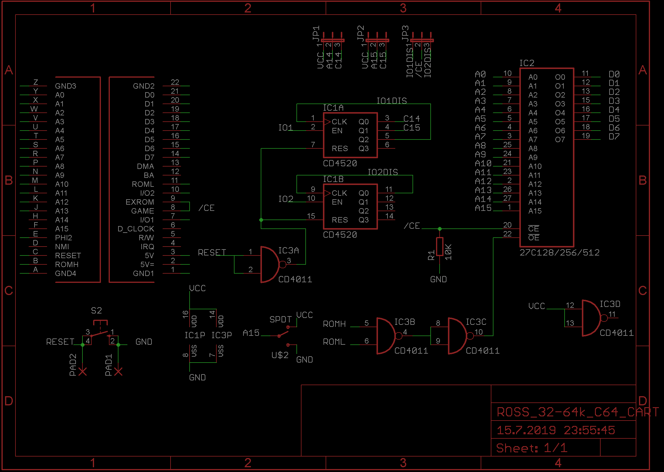
Readers with a keen eye will notice that the /IO1 and /IO2 lines are actually connected to the ENable input of the counter, and that the clock inhibit line is connected to the CLK input. This is done to save a couple of inverters, as /IO1 and /IO2 are active low, but the counters in the CD4520 are done in positive logic.
At startup, the first 16k bank is active. If any address from the /IO1 range ($DE00-$DEFF) is accessed, the second 16k bank will be visible. Depending on the type of EPROM used (32 or 64k), next access to /IO1 will either switch in the first bank again (32k EPROM), or present us with the third bank (64k EPROM), and the next access will bring in the fourth bank (or the second one again if 32k EPROM). Next access to /IO1 will either bring us the first bank and lock the banking mechanism, or, depending on the jumper configuration, remove the cartridge from the memory map. Similarly, the first access after RESET to /IO2 will remove the cartridge from the memory map, if the default jumper configuration is used.
Now onto the jumper block. It was made to be able to accommodate various types of EPROMs (16, 32 and 64k), and to select whether access to /IO1 or /IO2 will disable the cartridge. Default configuration is 32k cartridge, with disable at /IO2. I have redone it to be able to use pin headers and jumpers (and also hardwired it to the default configuration, with visible traces that can be easily broken). Again, this exact behavior (the default configuration of this cartridge) is emulated in VICE under the name “Ross”.
Unfortunately, browsing trough the classifieds I could not find any 64k cartridge advertised at the time. The only one that was advertised as 64k (Oxford Pascal) was recently found and archived, and is actually a 32k cartridge. For the purpose of testing the 64k version of this cartridge I have made a small loader that would copy a large game from the EPROM to the RAM and it was working very well, so full 64k cartridge is possible with this hardware. I hope that the VICE team will benefit from my findings, and hopefully extend the “Ross” type cartridge in their emulator, so we can have full 64k “Ross” type cartridge emulated in VICE very soon.
Possible configurations of this cartridge are:
- 16k ROM, disable on /IO2 access at any time
- 32k ROM, 2 16k banks, bank switching at /IO1, disable on /IO2 access at any time (default)
- 64k ROM, 4 16k banks, bank switching at /IO1, disable on /IO2 access at any time
- 64k ROM, 4 16k banks, bank switching on /IO1, disable at next access to /IO1 after the last bank


I have recreated the PCB to mostly resemble the original. The drill-to-break jumpers were replaced with pads for the pin headers, and hardwired to use the default configuration. The only thing I don’t like when routing a PCB is 90-degree angles on the tracks, and when a diagonal track is not at 45°, so I addressed these problems too. My opinion is that the 16/32k jumper should be omitted because the PCB described in Part 2 does the same but with only one IC. You may also wonder, why such a footprint for the RESET switch. This was custom made so that it can accommodate either a vertical or a horizontal tact-switch, or to make it easy to extend the switch with wires if you are using a cartridge enclosure. Also, the original cartridge had no provision for a switch to enable the user to have two different 32k cartridges if a 64k EPROM is used. This was also added on the recreated PCB. If you want to use this feature, you have to break the jumper at JP2 (it must not be connected in any of the two positions) and install a switch (above the C-64 text on the silkscreen).
As always, the files can be found on my GitHub page. Feel free to make modifications and make the PCBs.
Leave a Reply